Hardware, Banding and Fixtures in 3D
Carpentry drawings show their fittings and edge banding on a 3D page, and stone worktops their sink, hob and tap, and the base cabinets under them. Nothing has to be modelled: they are made from the marks the drawing already has (the Hinge Bore tool's bores, holes, banding lines, cut-outs) once the panels or the worktop are solids (EXTRUDE). Each fitting moves with the panel it is on, so it goes into place when the parts are put together and out with them in an exploded view. They show in every 3D export, the proof images and video, and the web viewer.
Fittings
| Mark | Shown in 3D |
|---|---|
| A Hinge Bore block | A concealed hinge in each cup: the cup bored 13 deep (not through, even when the bores are on the panel's own layer), its fixing dowels in the fixing holes, the arm reaching back over the hinge edge to the mounting plate on the carcass side's inside face (a full overlay door: the side under the door's edge, as thick as the door). |
Holes on a layer with LAYER3D n,AS="HARDWARE" |
A fitting in each, bored to its depth: a shelf pin (5 mm holes), a dowel (8 mm: 30 long, half out of the face), a cam fitting (15 to 25 mm: the cam in its housing and its bolt out through the nearest edge) or a hinge cup (35 mm). FIT="PIN", "DOWEL", "CAM", "HINGE" or "NONE" says which, whatever the size. |
| Loose holes and drill holes inside a panel, in a carpentry drawing | As on a hardware layer, by their sizes. |
Lines on a layer named for runners or slides ("Drawer runners"), or with AS="RUNNER" |
A drawer runner along the line, as long as it is, on the panel's face. |
Holes are bored down from the panel's top face as drawn (the face its pockets and housings are cut in); FROM="BOTTOM"
on the hardware layer bores them from the underside. DEPTH sets how deep (a hinge cup 13, a shelf pin 10, a dowel
12, a cam 13 by default).
Shelf pins go where the shelf sits: in a row of holes (three or more in line) only the middle hole gets a pin, on each
side. PINS on the hardware layer says which holes instead: PINS="ALL", or the holes' numbers from the row's lower
(or left) end, PINS="3,7".
Edge banding
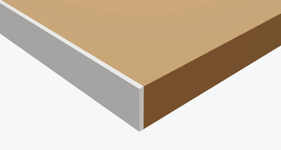
Banding is marked as the panel cut list reads it: a line along a side of the panel, on a
layer whose name says banding or edging (or with AS="BAND"). In 3D the side gets a strip of banding the panel's full
thickness, as far along it as the line runs (to the corner when the line stops short of it by less than a twentieth of
the side, up to 25 mm). The panel's outline is its finished size: the band lies inside it, filling the outer THICK of
the edge, and the panel's core is cut back by that much on each banded edge, so the panel with its banding is as big
as its outline (the panel cut list gives the cut sizes, less the banding). On the band layer, THICK sets its thickness (1 mm by default) and LOOK its material: an appearance, or a
colour, LOOK="#ffffff"; without one it looks like the panel.
LAYER 30,"Edge banding",[255,0,0]
LAYER3D 30,AS="BAND",THICK=2,LOOK="#f4f4f0"
Worktop fixtures
The cut-outs in a stone worktop (holes in its outline, or outlines on a layer AS="THROUGH") get their fixtures:
| Cut-out | Shown in 3D |
|---|---|
| Sink | A stainless steel bowl hung under the worktop (undermount), 200 deep, its rim 15 beyond the cut-out, with a waste. SINK="INSET" on the worktop's layer sets the sinks in from the top, their rim on the worktop. |
| Hob | A black ceramic glass top 20 beyond the cut-out on the worktop, with four cooking zones, its box down through the cut-out. |
| Tap hole | A mixer tap on the hole, its spout over the nearest sink. |
What a cut-out is for is read from a label inside it, in the words the stone quote reads ("Sink", "Basin", "Hob", "Cooktop", "Tap" …; a socket is left empty), else from its size: a round hole up to 65 mm across is a tap hole; a cut-out with a tap hole behind it is a sink; one at least 450 mm each way is a hob; one at least 200 mm each way a sink; smaller ones are left empty.
Your own sink or hob: place its model with PRODUCT in the cut-out, and it takes the library's place.
Fixtures are fitted in stone drawings, to worktops of a stone appearance, or where the worktop's layer says
FIXTURES=1; FIXTURES=0 leaves them out.
Base cabinets
CABINETS on the worktop's layer stands it on base cabinets that high (the height under the worktop). Each piece of
the worktop is filled along its length with carcasses no wider than CABINETW (600 by default), as deep as the piece
less its front overhang (OVERHANG, 40), their backs to the wall. The carcasses are the library's
Cabinet carcass design, put together as its 3D page shows it, at each cabinet's
sizes. The front of a piece is the side towards the inside corner of an L or U, else the side its cut-outs are nearer,
else its lower side as drawn. The worktop, and everything fitted to it, sits on the cabinets.
TH=30
LAYER3D 0,AS="BODY",THICK=TH,LOOK="quartz-white",FIXTURES=1,CABINETS=870
LAYER3D 8,AS="GROOVE",WIDTH=6,DEPTH=4
The library's L-shaped worktop does this: change CAB to raise the cabinets, or set it to 0 for the worktop alone.
See also
- Making drawings 3D: the modes and the LAYER3D settings.
- Assembling in 3D: parts put together by their mates, and exploded.
- Products in the pack: your own 3D models placed in the scene.
- Materials, measuring and sections: the looks of the panels, the worktop and the fittings.