Products in the Pack
Put the product your pack is for - a bottle, a tool, a phone - into the drawing as a 3D model, and the 3D page shows it in the folded carton or the foam insert, checks that it fits (where it runs into the pack, how much room it has on each side) and cuts its foam pocket for you.
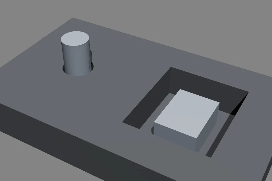
Placing a product
- On the drawing page (not the 3D page), select the point the product should stand on, if there is one.
- Choose 3D › Models and Products › Place Product… and choose its 3D model: a file or a web address. Tick Embed in Drawing to keep it in the drawing (the drawing then needs no other file), or leave it linked (read again from the file whenever the drawing is opened, so a changed model shows).
- The product is put on the point you selected (it moves with it), or else in the middle of the drawing. It is drawn as the outline of its box seen from above with a cross at its point; it is never cut, folded or exported.
On the 3D page it stands with the middle of its box (seen from above) on its point, and drops onto whatever is under
it: the base of the folded carton, the top of the foam, or the floor of its pocket. As the slider reaches the end, it
drops in from above. Its look is a plain grey (product-grey); give it another with its LOOK setting.
To put it on a particular face instead - on a shelf of the insert, in a tray that slides into a sleeve - draw it
beside the pack and give it a MATE under its point that goes IN a mate on that face: it is put
there as the parts are put together, and its fit is checked where it ends up.
The models it reads:
| Format | Read as |
|---|---|
STEP (.step, .stp) |
AP203, AP214 and AP242: solids and surfaces (planes, cylinders, cones, spheres, tori and extrusions made exactly; B-spline faces from their edges), faceted and tessellated bodies, assemblies with each part where they put it, in the file's units. |
STL (.stl) |
Binary or text; millimetres, Z up. |
OBJ (.obj) |
Y up; millimetres, or metres if it is under 10 units across. |
glTF (.glb, .gltf) |
Metres, Y up, as the standard says; its scene's nodes placed. |
COLLADA (.dae, .zae) |
In the units and up axis it says. |
IFC (.ifc) |
IFC2X3 and IFC4 building models: each element a part, shown see-through (Steel structures). |
ParametrIQ drawings (.piq) |
Made 3D: a structure's member (Steel structures). |
| PRC, U3D | As 3D › Models and Products › Import Model… reads them (desktop only). |
Its settings
Select the product and change them on the PRODUCT statement, or in the drawing file. Each is an expression, so a variable keeps it parametric.
| Setting | What it does |
|---|---|
ROT |
Turns it about the vertical, in degrees anticlockwise. |
TILTX, TILTY |
Tilts it about the x and y axes first: a model drawn lying down stood up. |
Z |
The height of its underside. Without it, it drops onto what is under it. |
SCALE |
Its size (1: as the model is). |
LOOK |
The appearance it is shown in. |
CLEARANCE |
The room it needs from every wall: less is reported. |
PART, STEP |
The part it moves with when parts are put together (assembling), and when it goes in. |
ORIGIN |
TRUE: the model's own origin on its point, at Z (0 without it): nothing centred or dropped. |
Does it fit?
Whenever the 3D page is made, each product is checked against the folded panels and the solids (foam, inserts, boards) as they are at the end of the slider, with the parts put together:
- Clashes: where the product runs into the pack (an edge of one passing through the other, or the product inside a solid). They are shown red on the product and said in the 3D page's message bar. Faces that only touch - the product standing on the foam, a side against a wall - don't count.
- Clearance on each side: from the product's corners to the nearest surface along x (left, right), y (front, back)
and z (below, above). The least of them, leaving out below (what it stands on), is its room to the walls; less than
its
CLEARANCEis said in the message bar.
3D › Models and Products › Show Product Fit… shows the figures for each product as a report, to save as CSV, a web page or text.
Cutting its foam pocket
- Draw the foam insert as bodies on a layer with 3D settings (
LAYER3D 20,AS="BODY",THICK=30: see Making drawings 3D), and put the product over it. - Select the product and choose 3D › Models and Products › Product Pocket in Foam….
- In the dialog, type the Clearance round it and the pocket's Depth from the foam's top, and choose its Shape: Section within the depth shapes the pocket to the part of the product within that depth (a bottle's body, not its wider cap above the foam); Whole outline from above follows its whole outline seen from above.
- The Preview shows the pocket as you change them: the product's traced outline dashed, the pocket round it in orange, over the drawing's lines with the foam's outline (the smallest closed outline that holds the pocket) filling the picture. Choose OK to cut it.
The clearance and the depth are each a number in the drawing's units, a variable's name (FOAMGAP) or a formula
(T*0.8), worked out in the drawing as you type: one that can't be worked out, or a depth that isn't more than 0, is
said under them in the dialog, and the preview waits for it. Whatever you type is written into the pocket's variables
as it is (SHC1=FOAMGAP), so the pocket follows the variables it uses. The dialog remembers what you typed and chose
for the next pocket (millimetre and inch drawings apart).
The product's outline is traced (straight lines and arcs) and drawn on points defined on the product's point - turned
by its ROT - so moving or turning the product moves its pocket. The pocket is a
shadow pocket of it: the clearance outside it all round (SHC1), its depth
noted in it (SHD1), both variables, on the pocket layer (the first layer whose 3D settings say AS="POCKET", else
the Partial cut layer, given LAYER3D …,AS="POCKET",DEPTH=SHD1). EXTRUDE cuts it into the foam, and the product
drops onto its floor.
See also
- PRODUCT: the statement.
- Making drawings 3D: the 3D page's stages and the LAYER3D settings.
- Pocket Tool and Foam Layers Tool: pockets by hand.
- Pages › 3D pages: Import Model… shows a model beside the design without placing it in the drawing.