Sheet Metal and Living Hinges in 3D
A 3D page folds a sheet-metal flat pattern up the way a press brake bends it, and bends a laser-cut living hinge round as one smooth bend. What it shows goes into every 3D export, and a sheet-metal part is written to STEP as an exact solid. See Making drawings 3D for the other modes.
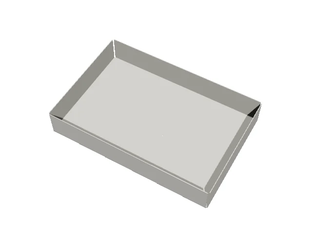
Which drawings fold as sheet metal
A drawing folds as sheet metal when its industry is Sheet metal or HVAC, or when it has a K variable (a K-factor, as a drawing made with a sheet-metal material has: see Materials). Its bend lines are found as the bend table finds them: straight lines on the Crease layer bend up, on the Reverse crease layer down, each to the angle, way and radius its Bend Line note gives (else 90°); R, K and T are the drawing's, and a bend of its own radius takes its material's K-factor table's K-factor at its own R / T.
True bend radii and thickness
Each bend is bent round its inside radius R, the sheet a solid T thick:
- The strip of the blank a bend takes up is its bend allowance, with the bend line in its middle, as the Flat Pattern and Bend Line tools draw it. That strip is bent into a quarter (or whatever the angle makes) of a cylinder: its inside face round R, its neutral layer (K of the way through the sheet from the inside) keeping its length.
- So the flanges come out at the flat pattern's outside sizes: a U channel drawn 60 × 40 outside folds to 60 × 40.
- In the 3D view each bend is folded along lines across its strip, one every 5° it turns, without grooves, so the bend shows round.
The slider makes the bends one after another in the bend table's order (the bends nearest the edges first), unless a
bend line has its own step (RULE STEP=…).
Collisions and the bending order
As a sheet-metal part is shown, its bending is checked: each bend is swept from flat to its angle in the bend table's order, the bends before it made, and the flanges are checked against each other. What is found is said in the message bar:
- … hits … while bend n is made (at a°): a flange gets in the way while the part is bent in this order. When another order avoids it, that order is given (Bending in the order 2, 1, 3, 4 avoids it.).
- … overlap once the part is folded: the flanges run into each other even when it is made: a flange is too long, or a relief too small.
The check takes each face as the middle of the sheet (half its thickness in), and a bend as narrow flat strips: two faces clash where they cross, or lie closer than the sheet's thickness face to face. Each bend is also made on a simulated press brake, its punch and die from a small tooling library (named on its bend line, else chosen), and a flange that runs into the punch, the die or the machine's beams is said too: see Press-Brake Simulation. Parts with more than 24 bends are not checked.
Hems
A hem is a bend folded right back over the sheet. Give its bend line a Bend Line note of 180° (or draw its note yourself):
| Hem | Note | In 3D and STEP |
|---|---|---|
| Closed | UP 180° R0.2 |
The flange folded flat onto the sheet (a radius of almost nothing). |
| Open | UP 180° R2 |
The flange folded back, a gap of twice the radius under it. |
| Teardrop | UP 200° R2 |
The bend goes on past 180°, so the flange comes back down to the sheet: a loop at the edge. |
A note may give up to 270°. Hems are bent round their radius like any other bend, in 3D and in the exact STEP solid; the press-brake check leaves bends past 150° out (they are flattened, not bent in a V).
Louvers and embosses
Louvers and embosses (ribs, rectangular embosses, round dimples) drawn with the Louver tool are formed in 3D when they have a Forming Height (more than 0 pressed up, towards you; less than 0 down):
- the sheet is cut where each is pressed out: a louver along its lance and round the hood, an emboss round its outline;
- each is a solid of its own in that hole, carried by the flat it is on as the part folds: a louver's hood rises from the sheet behind to its height at the lance, its ends ramped down; an emboss is a cup the sheet's thickness thick, its wall straight up its outline, its top flat;
- in STEP each is an exact solid beside the part's: an emboss of planes and cylinders (its corners' arcs), a louver of planes.
Features on a bend's zone are not formed. A drawing whose louvers have no forming height shows them flat, as drawn.
Exact STEP
File › Export › Export… › STEP Files (Folded Part) writes a sheet-metal part as an exact solid (an advanced B-rep, as AP214 and AP242 read it): each flat's faces are planes, each bend's inside and outside faces are cylinders round its true radius, round holes are cylinders, and the edges join exactly. A CAD program can measure the bend radii, unfold it in its own sheet-metal tools, and mate to its faces. See STEP.
The other way round, File › Import › Import 3D for Unfolding… unfolds a sheet-metal part's STEP file into its flat pattern, with bend lines and notes: see Unfolding 3D Models.
Living hinges
A living hinge has a Bend Angle (a variable, LHA1; 90° unless changed: more than 0 bends up, towards you, less than 0 down). In 3D its band bends round as a curved bend does: it is folded along lines between its rows of slots, each its share of the angle, all in one step. The slots themselves are not shown in 3D.
See also: Sheet Metal, Making drawings 3D, Pages.