Assembling parts in 3D
On a 3D page, the parts of a drawing can be put together once they are made: a lid on its box,
the sides of a laser-cut box stood up round its base, a cabinet's sides, rails and back fitted to its bottom, a beam
on its supports. This is the ASSEMBLE mode. Each part is made as it is drawn, lying flat
(folded, or extruded to its thickness); then, at the end of the slider, the parts are put
together where their MATEs say, one step at a time. The Explode slider then draws them apart.
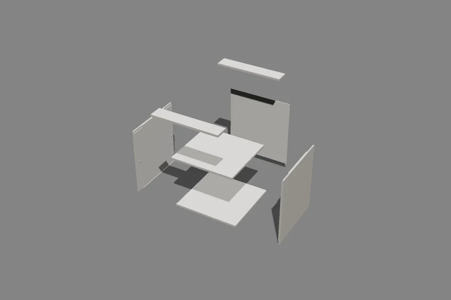
Parts
A part is what moves as one:
- a folded blank (its panels, folded up from its base);
- a solid: a board, a sheet, a plate or a beam made from a closed outline. Solids on a layer whose
LAYER3D settings give the same
PARTname move together.
Draw each part as it is cut, side by side on one page, and put a mate on each where it meets another.
Mates on solids
A mate is a place, a direction and an inside. On a folded panel its height is above the panel, on
its inside. On a solid, imagine it lying as drawn: its height is how high above its underside the mate is (0
its underside, T its top face), and its inside is up. A point anywhere on the part, or inside its outline's extent
(a corner of a finger-jointed edge, say), puts the mate on it.
A mate that goes to another (TO face to face, IN the same way round) puts its part with that one's; then:
| Setting | What it does |
|---|---|
TURN=angle |
Turns the part about the other mate's direction, in degrees: TURN=90 stands a side up on its base's edge. |
ALONG=distance |
Moves it along the other mate's direction (a shelf slid along its housing). |
ACROSS=distance |
Moves it across the other mate's direction, to its left. |
STEP=n |
When it is put there: 1 first, then 2 …; mates with the same step go together; mates without one each take a step of their own, after, in the drawing's order. |
Steps and the slider
The parts are made over the first four fifths of the slider, where they lie in the drawing. Over the last fifth they
are put together, a step at a time: each part rises to just off its place (above it, or, going IN without a turn,
back along the other's direction), turns, and moves in. Play Steps pauses after each. A part put with one that
is itself put somewhere later goes with it.
Exploded view
The Explode slider beside the fold slider (shown when there is more than one part) draws the parts apart: the
parts the others are put on stay, and each of the others moves out from the middle of the whole, the further the
further it is from the middle; a layer's
LAYER3D EXPLODE= setting gives its solids' distance. Back at the left, they are together.
Laser-cut boxes
Draw the panels with the Finger Joint Tool, give the Cut layer its thickness
(LAYER3D 0,AS="BODY",THICK=T,LOOK="birch-plywood"), and stand each side on the base's edge:
LAYER3D 0,AS="BODY",THICK=T,LOOK="birch-plywood"
P60=#O
MATE @60,"front edge",P60,0,0,8
P64=[0,W+G]
MATE @64,"front",P64,T,0,8,IN "front edge",0,TURN=90,STEP=1
The base's mate is on its corner, on its underside, pointing along its edge; the side's is on its own corner, on its
top face (T), pointing the same way. Turned 90° about the edge, the side stands up with its outside flush with the
base's edge, its slots round the base's fingers. Run Parametric › Laser cutting › Finger-jointed box does this
for every side.
Carpentry
Boards are bodies the board's thickness; housings, rebates and grooves are pockets on layers
of their own, so the joints show; a back panel of thinner board goes on a body layer of its own. Mate each part to
the one it sits on: the sides stood up (TURN=90, or -90 for a side drawn the other way round) on the bottom's
housings, the rails lifted to the top (the gap), the back stood up at the back (ACROSS=). Dovetails and finger
joints drawn on the boards' outlines interlock as they are drawn; a mortise drawn as a pocket takes its tenon.
Run Parametric › Carpentry › Cabinet carcass is put together this way.
Structural steel
In a structural steel drawing whose classification names a profile (CLASSIFY "profile","IPE 300"), each closed
outline on the Cut layer is a piece of that profile, as the IFC export makes it: the outline is
the web seen from the front (its length along x, its depth up), the section's sizes come from the profile table (or
the designation's numbers: L 80x80x8, RHS 120x80x5, CHS 114.3x5), the copes cut back the flanges with the web,
and holes go through the web. Round tubes and bars are cylinders. The piece lies on its side as drawn, its flanges
towards you. A plate drawing (no profile) is extruded the plate's thickness (T), its holes through it. Mate plates
and beams as any other parts: an end plate on a beam's end, a fin plate on a column.
Examples
T=6
P1=[0,0]
P2=[200,0]
P3=[200,120]
P4=[0,120]
POLYLINE [P1,P2,P3,P4],TRUE
P5=[0,140]
P6=[200,140]
P7=[200,220]
P8=[0,220]
POLYLINE [P5,P6,P7,P8],TRUE
MATE @90,"near",P1,0,0,8
MATE @91,"front",P5,T,0,8,IN "near",0,TURN=90
A base and a front, both 6 thick: the front stood up along the base's near edge, its outside flush with it.
See also
- 3D modes: how a drawing becomes 3D.
- MATE and the Mate Tool.
- GROUND and the Identify Base Tool: the panel each shape stands on.
- LAYER3D: a layer's thickness, material, part and exploded distance.
- Pages › 3D pages.