Layers
The Layers panel lists the drawing's layers, with three check boxes for each:
- Visible: whether the layer is drawn. The Construction layer, for construction geometry, starts hidden. The Split, Intersect, Fillet and Chamfer tools move to it the elements they cut that something is still defined on (lines, arcs and circles that nothing refers to are deleted instead); it is never exported. Edit > Tidy Drawing takes out what is on it that nothing needs any more (see Points).
- Plot: whether the layer's elements are written to G-code and HP-GL. Dimension and Construction start not plotted.
- Spot: whether the layer prints as a spot colour of its own, named after it, in PDF, EPS and Illustrator files (see Bleed, Safe Zones and Spot Colours).
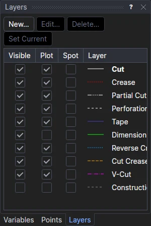
All three are saved with the drawing. A single element can also be hidden, or left out of plotting, whatever its layer: see Properties.
Each layer can also have machining settings of its own (tool, speeds and feeds, depths, cutter side, drilling, pocketing), which its elements are cut with in G-code unless they have their own: set them for every layer in one grid with Production › Tool Options. They are saved with the drawing too (see LAYER).
The current layer
New elements go on the current layer, shown in bold in the panel. Pick a layer and click Set Current (or right-click it and choose Set as Current Layer) to draw on it; a tool's Layer option in Tool Options changes it too.
Making and changing layers
A drawing starts with the standard FEFCO layers (Cut, Crease, Partial Cut, Perforation, Tape, Dimension, Reverse Crease, Cut Crease, V-Cut) and Construction, and you can add your own: a varnish, a white ink, a registration mark, a second cutting tool. The buttons above the list, and the menu when you right-click it, do the work:
- New… opens the layer dialog for a new layer, numbered after the others (from 1000).
- Edit… (or double-click a layer's name) opens the same dialog for the layer picked.
- Delete… deletes the layer picked (see below).
- Set Current makes the layer picked the current layer.
In the dialog:
| Setting | What it does |
|---|---|
| Name | What the layer is called in the panel and every layer list. It must differ from the other layers' names. |
| Number | What the drawing's elements and its LAYER line refer to the layer by. A new layer can have any number not in use (32768 to 36864 are kept for the app's own layers); an existing layer keeps its number. |
| Screen colour (dark theme) and (light theme) | The colour the layer is drawn in on a dark and on a light background. |
| Line style | Solid, dashed, dotted, dash-dot, or Custom: dash and gap lengths in turn, in pixels (8,2,2,2). |
| Print colour | How the layer prints in PDF, EPS and Illustrator files: as on screen (its light-theme colour), or an RGB, CMYK or grey colour of its own, each value from 0 to 1 (a grey level: 0 black, 1 white). |
| Visible, Plot, Print as a spot colour | As the panel's check boxes. |
The standard layers can be changed and renamed too: the names are the drawing's own, and die making and machining go by the layer's number, not its name. (The dimension tools, such as Ortho Dimension, look for a layer called Dimension to put dimensions on; renamed, they use the current layer.) A new layer appears straight away in every layer list: the tools' Layer option, the Properties panel and Production › Tool Options.
Standard production layers
Some tools draw on layers of their own, and the library's designs use them too. Each has a fixed number (from 9900: clear of the FEFCO layers, the numbered pen and tool layers files bring in, and the layers you add, which start at 1000 and are never offered a number from 9900 to 9999), and it is added to the drawing, as below, the first time something is drawn on it; a drawing that already has a layer of that number, or of that name, keeps its own. The exports and reports know each by its number (or by its English name, for a layer you made yourself):
| Number | Layer | Drawn by | Colour | Plotted | What the outputs do with it |
|---|---|---|---|---|---|
| 9900 | Registration | Registration Mark, Label Layout's eye marks, the vinyl decal designs | White (black on a light background), printed in every ink | Yes | Never cut or part of a die; printed as the marks in print-and-cut files |
| 9901 | Drill | Drill Hole, Fixing Holes | Sky blue | Yes | Drilled: a hole at each circle's centre, the circle's size (G-code); never a rule |
| 9910 | Etch | Part Mark, Weld Preparation's label | Magenta | Yes | Marked, not cut through: engraved by a laser, marking in DSTV |
| 9911 | Form | Louver | Amber, dashed | No | Formed by a press tool: left out of cutting |
| 9912 | Window film | Window with Patch | Pale blue, dotted | No | The film glued over a window: left out of cutting |
| 9913 | Engrave | The laser cutting designs' lettering, borders and grooves | Violet | Yes | Engraved (filled line by line) by the laser exports and the laser job report; left out of print-and-cut |
| 9914 | The vinyl decal designs' print areas | Green | No | Printed as artwork in print-and-cut files; never cut |
Their names are added in the app's language. Layer 8 (Dimension) is for dimensions and guides only: no export cuts, engraves or prints it unless you choose to in its options. To engrave something of your own, draw it on the Engrave layer (add it with New…, number 9913, if the drawing hasn't it yet), or on a layer whose name says so (Engrave, Etch, Raster).
Deleting a layer
Delete… asks first. A layer with elements on it, on any of the drawing's pages, can't simply be deleted: you are offered to move them to another layer you choose, then delete it, as one step. The Construction layer, which every drawing keeps, and the current layer (make another one current first) can't be deleted.
Making, changing and deleting layers can all be undone (Edit › Undo), and the layer table is saved with the drawing. (The Visible, Plot and Spot check boxes, and the current layer, are saved too but are not steps to undo.)