Flat Pattern Tool
Use the Flat Pattern Tool to draw the flat blank of a part bent from one sheet: an angle, a channel, a Z, a hat section, a box's side with its flanges. Type its flanges' sizes as the drawing of the bent part gives them, and the blank is drawn as wide as they develop to, allowing for each bend from the K-factor, with a bend line in the middle of each bend and a note of which way it goes. It is a tool of the sheet metal and HVAC trades.
Usage
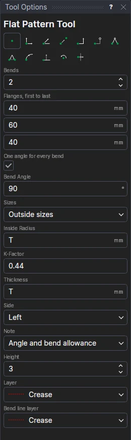
- Set the number of Bends, then fill in the Flanges, First To Last (one more than the bends: 40, 60 and 40 for a channel 60 wide with 40 legs).
- Leave One Angle For Every Bend ticked and fill in the Bend Angle, or untick it and fill in each bend's angle. An angle less than 0 is a bend down (-90 for the second bend of a Z).
- Choose whether the flanges are Outside Sizes (measured to where the outside faces meet, as a drawing of the bent part usually dimensions them) or Inside Sizes.
- Fill in the Inside Radius, the K-Factor and the sheet's Thickness. In a sheet-metal drawing (see Materials) they start as its R, K and T.
- Choose the Side of the edge the blank is drawn on, the bend lines' Note (as the Bend Line Tool's) and its Height, the layer of the outline and the Bend Line Layer (the Crease layer to start with). The notes go on the Dimension layer, so they aren't cut.
- Click* the start of the blank's edge, then its end: the bends run along it, as long as it is.
How the blank is worked out
Each flat is its flange's size less the set-back at each of its bends, and each bend adds its bend allowance:
- the set-back is tan(angle / 2) × (R + T) for outside sizes (R + T for a right angle), tan(angle / 2) × R for inside sizes;
- the bend allowance is the length of the bend along its neutral line, angle × (R + K × T), the angle in radians;
- so each bend takes its bend deduction (twice the set-back less the allowance, see BENDDEDUCTION) off the sum of the flanges.
Each bend line is drawn in the middle of its bend, where a press brake's operator lines the blank up. For example, a channel of 2 mm mild steel (K 0.42, R 2) with flanges of 40, 60 and 40 has a blank 132.92 wide, its bend lines 38.23 and 94.69 from the edge: the same as the Run Parametric library's U channel design.
The angles must be less than 180°. For a hem (folded right back), draw the hem's flange and its bend with the Bend Line Tool, or use the library's Hemmed edge panel design. K-factors depend on the material, the tooling and how it is bent: check them against your press brake.
It follows the drawing
The blank is drawn on the two points you marked and on new labelled variables: the flanges (FLG1, FLG2 …) and the angle (BANG1, or BANG1, BANG2 … one for each bend), with R, K and T (made if the drawing hasn't them yet). Each bend's deduction (BD1 …) and the blank's width (FLAT1) are variables worked out from them, so a dimension or a note can use them. Change a flange, an angle or the thickness and the blank and its bend lines are worked out again; move a point and they follow it.
*Depending on the chosen snap mode, several clicks may be required to define the point parametrically. Read more about Snap Modes