Dimensions in 3D
Dimensions and notes can be put on the 3D model itself, as product manufacturing information (PMI): the height of a folded box, the angle a flap folds to, a hole's diameter on a routed panel, a note pinned to a face. They are measured on the model as it is made, so they show the sizes the customer gets, not the flat blank's; and they stand on the flat drawing's points, so they follow its variables.
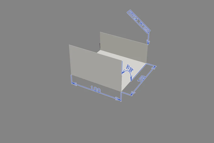
Adding one
Write a DIM3D statement on the page the 3D page shows (DIM3D @20,"LINEAR",[P0,P1],0), or
measure on the 3D page and keep the measurement:
- 3D › Measure and Annotate › Measure Distance (or Measure Angle) and click the points on the model.
- Press Keep as Dimension on the measuring bar.
The dimension is written on the folded page's points (the drawing's own points where there are some at those places, else new ones), with the heights the clicks were at; it is one step to undo. A point on a bend or on an imported model can't hold a dimension (the bar says so).
Where they show
- The 3D page draws them over the model in dark blue, as it is now: fold the model and they follow, their values changing as it folds. 3D › Measure and Annotate › Show Sizes and Notes shows or hides them.
- Proof pictures and videos (Proofs) draw them over each picture.
- 3D PDF (3D PDF): each is in the model as thin rods (lines and text), so every 3D viewer
shows it, and is a 3D measurement of the PDF's view (ISO 32000-2's linear, angular and radial dimensions and
comment notes), which Acrobat lists with the view; a
VIEWgives a view of its own showing just those. Export 3D Model as PRC has them too. - STEP (STEP): the file is then AP242 with semantic PMI (a linear distance, angle, radius or
diameter with its value and tolerance) and its presentation as polylines on an annotation plane, gathered in a
saved view for each
VIEW.
How they are placed
Each point is taken to where it is on the model: on its panel's outside face (or the height given above the panel's
middle, inside), on its solid's top (or the height given). A distance is drawn in the main plane through it that
faces the usual front-right view most, set off away from the model's middle; an angle in the plane of its three
points; a radius or diameter on the surface at its centre; a note's leader out of its surface. PLANE and DIST
change that. A dimension whose points are on nothing (a page that doesn't make them) is left out and said on the 3D
page.
See also
- DIM3D: the statement and its settings.
- Materials, measuring and sections: measuring on the 3D page.
- Making drawings 3D.