Machining Tool Options
Production › Tool Options… sets each layer's machining settings for G-code in one grid: the tool, speeds and feeds, depths and so on that every element on the layer is cut with. Set them once (a 6 mm end mill outside the line for the Cut layer, a creasing wheel for Crease, a drill for a layer of holes), and only the elements that differ need settings of their own. Export them to a tooling file to use them in other drawings, or make them the default for new drawings (see Reusing tooling).
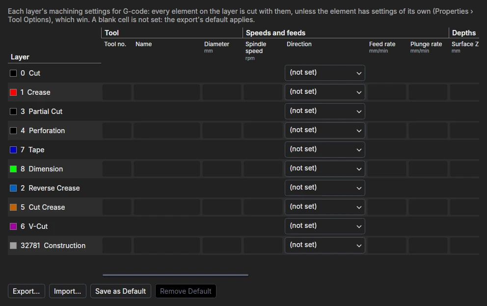
(The Tool Options panel is something else: the options of the drawing tool in use.)
The grid
Each row is a layer of the drawing, with its colour, number and name; each column is a setting, under its group. The layer names and headings stay in place as you scroll across and down. A blank cell is not set: the export's default applies (see below).
| Group | Settings |
|---|---|
| Tool | Tool no. (the T word; tools without one are numbered by size), Name (written as a comment), Diameter. |
| Speeds and feeds | Spindle speed (rpm), Direction (clockwise, M3, or anticlockwise, M4), Feed rate and Plunge rate (drawing units a minute). |
| Depths | Surface Z (the top of the material, 0 if not set), Depth (the bottom of the cut, negative below the surface), Step down (the deepest cut in one pass), Safe height (Z for rapid moves). |
| Cutter side and coolant | Cutter side (on the line, inside, outside, left or right), Coolant (M8). |
| Drilling | Drill (drill every point on the layer, and every circle's centre), Hole diameter, Peck depth (G83), Dwell (seconds at the bottom, G82). |
| Pocketing | Pocket (clear the inside of closed shapes in this style: see Pocketing), Step over (the distance between passes). |
| Drag knife | For a vinyl cutter's or plotter's knife, in the HPGL export: Overcut (how far a closed cut runs on past where it started, so it is cut through where it meets itself) and Blade offset (how far the blade's tip trails behind its axis: 0.25 mm for a 45° blade, 0.5 mm for a 60° one). |
Lengths are in the drawing's units. Hover over a heading to see what it is, and its key in the drawing file. OK applies every change as one step to undo; a cell that holds something its setting can't take (a word for a number, a negative diameter) is pointed out, and nothing is changed until it is put right.
Reusing tooling between drawings
The buttons under the grid keep a shop's tooling apart from any one drawing, so it is set up once:
Export… saves the grid's settings, as they are in the grid, to a tooling file (
.piqtools): every layer that has settings, with its number, name and colour. Layers with no settings are left out.Import… reads a tooling file into the grid. Each of its layers goes to this drawing's layer of the same name (capitals and spaces at the ends don't matter), or, if none has that name, to the layer with the same number. You are asked what to do, when it matters:
- with layers the drawing doesn't have: add them (they are marked (new) in the grid, keeping their number if the drawing hasn't used it, else numbered after the drawing's other layers), or leave them out;
- with matching layers that have settings already: replace them with the file's (a setting the file leaves blank is cleared), or merge (the file's settings are set, the others kept).
The drawing's layers that aren't in the file are left as they are. Lengths and feeds are converted when the file was saved from a drawing in other units (millimetres or inches). The line under the buttons says how many layers matched and were added, and which were left out. Nothing changes in the drawing until you click OK, which applies the import, with any changes you made after it, as one step to undo.
Save as Default makes the grid's settings the tooling every new drawing starts with (File › New, and a new drawing from the materials you work in). It is saved as
Default.piqtoolsin your Extensions folder (File › Extensions › Open Extensions Folder), so you can also put a tooling file there yourself. Remove Default deletes it: new drawings start with no settings again. Drawings you open keep their own settings.
A tooling file is text, in the drawing language: a units line, then a LAYER line for each layer,
with its settings after TOOL. You can write or edit one by hand:
//Units// MILLIMETERS
LAYER 0,"Cut",[255,255,255],LIGHT=[0,0,0],TOOL NO=1,NAME="6 mm end mill",DIA=6,FEED=1200,DEPTH=-3,SIDE="OUTSIDE"
LAYER 1,"Crease",[255,0,0],PATTERN=[2,2],TOOL NO=4,NAME="Creasing wheel",DEPTH=-1
LAYER 500,"Holes",[0,200,200],TOOL DRILL=TRUE,HOLE=5,DEPTH=-12,PECK=3
Layer names are matched as they are written, so a file made in one language matches the standard layers of a drawing made in another by their numbers.
Which settings an element is cut with
For each setting, the first of these that gives it:
- the element's own tool settings (the Properties panel's Tool Options…, or
TOOLafter the element in the drawing file); - its layer's, from this grid;
- the export options': the Pocket layer chosen for that export, then the Default tool.
To have an element follow its layer again, select it and choose Use Layer Settings in the Properties panel (or on the drawing's right-click menu): its own settings are cleared.
A layer with settings is exported even if it is one that is normally left out (Tape, Dimension), as long as it is plotted (see Layers). Post-processors, reports and design rules see each element's settings the same way: its own over its layer's (see Post-processors).
In the drawing file
A layer's settings are saved on its LAYER line, after TOOL, with the same keys elements use:
LAYER 22,"Router",[255,128,0],TOOL NO=2,DIA=6,RPM=18000,FEED=1200,DEPTH=-3,STEP=1,SIDE="OUTSIDE"
See LAYER and Element settings.