Registration Mark Tool
Use the Registration Mark Tool to place registration marks: the marks a digital cutter's camera reads to find a printed sheet (Zünd, Kongsberg, Summa and the like read dots), or a printer's targets for lining up plates. The marks go on the Registration layer, which is added to the drawing if it hasn't one. It is a tool for every industry.
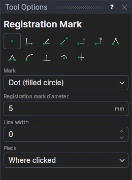
Usage
- Choose the Mark:
- Dot (filled circle): what most cutters' cameras read.
- Ring: a circle, as thick as the Line width.
- Target (circle and crosshair): a circle with a crosshair reaching 1.5 times its diameter across.
- Fill in the Registration mark diameter, and the Line width the marks are printed with (0: a hairline).
- Choose where to Place them:
- Where clicked: click* where each mark's centre goes: a point, a corner, a centre or anywhere.
- Four corners of the selection, Three corners of the selection: select the design first, fill in the Registration marks' offset (how far out from the design's extent the marks' centres are), then click anywhere. Four marks go round the design's extent, or three (none at the top right, so the cutter can tell the sheet's way round).
- Rows along the selection's length (a long job, in frames): for a vinyl roll or other long job. Select the design, fill in the offset, the Registration marks' spacing along the length (the most the rows may be apart) and Marks across (2: one each side; 3: the middle too), then click anywhere. Rows of marks go across the design's longer side, one at each end and as many between as keep them no further apart than the spacing, spread evenly. Each two neighbouring rows make a frame that camera registration measures and corrects on its own. Three across give each frame six marks, so a badly measured one shows in the fit's error.
The diameter, the offset and the spacing become variables (REGD1, REGO1, REGS1) that the next marks share: change the diameter or offset and every mark changes. (The number of rows along a length is worked out when they are placed; the rows stay spread evenly over the length when the design is resized.) Marks placed at a click are defined on the point clicked; marks at the corners are defined on the design's outermost points, so they follow the design when it is resized.
In output
The Registration layer prints in registration colour (on every plate) in PDF, EPS and Illustrator files, and is kept as a layer of its own in DXF and the other formats, for the cutter's software to find. It is never cut: G-code and HP-GL leave it out as a cut, and it is not part of a die (Make Die) or a dieline.
A machine profile with camera registration finds the marks (the circles on the Registration layer) and has a camera measure them before the job is written: see Camera registration.
*Depending on the chosen snap mode, several clicks may be required to define the point parametrically. Read more about Snap Modes
See also: Drill Hole Tool, Layers, Industries and Tool Sets.