Weld Preparation Tool
Use the Weld Preparation Tool to mark an edge that is to be bevelled for a butt weld: the bevel line, where the bevel meets the plate's face, drawn parallel to the edge, and a label giving the preparation, its angle, root face and root gap. The bevel cutter or the burner works to the line, and the label tells the shop what to cut. It is a tool of the structural steel and pipework trades.
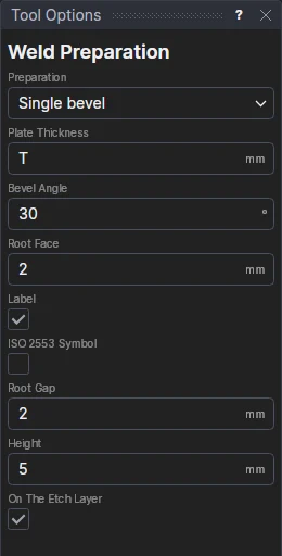
Usage
- Choose the Preparation: Single bevel (from one face) or Double bevel (K) (from both faces, the root face in the middle). For a V or an X preparation, bevel both parts' edges the same way.
- Fill in the Plate Thickness (a pipe's wall thickness; the drawing's thickness variable T, if it has one), the Bevel Angle from square (30° to 35° is usual for a single bevel, so a V is 60° to 70° included) and the Root Face (the land left square, 1.5 to 3 mm).
- Leave Label ticked to write the preparation beside the bevel line, along the edge.
- Tick ISO 2553 Symbol to draw the weld symbol as well (see below).
- With a label or a symbol, fill in the Root Gap (the gap the fitter leaves at the root: given in the label and the symbol, not drawn) and the text Height (the symbol is sized from it).
- Leave On The Etch Layer ticked to put the marks on the Etch layer, added if the drawing hasn't one (marked, not cut); or untick it and choose another layer.
- Click each edge to bevel: inside a closed outline, anywhere along it; on an open edge, on the plate's side of it. The bevel line is shown as you move over an edge.
The edge can be a line, a straight side of a polyline (such as a rectangle), an arc or a circle (a pipe's end, a hole). The bevel line is drawn in from the edge by
- (thickness − root face) × tan(bevel angle) for a single bevel, and
- half that for a double bevel, whose bevels from both faces meet the faces on the same line.
For example, a 20 mm plate with a 30° single bevel and a 2 mm root face has its bevel line 18 × tan 30° = 10.4 mm in from the edge, and its label reads 30° single bevel, root face 2, gap 2.
It follows the drawing
The thickness, angle, root face, gap and height are kept in new labelled variables (WPT1, WPA1, WPF1, WPG1, WPH1) that the next edges share. The bevel line and label are drawn by a block on the edge's points (an arc's or a circle's bevel line is an offset of it): change a variable, or move the edge, and the marks and the label's numbers follow. The label is turned along the edge as it runs (its TEXT's rotation is worked out from the edge's direction): turn the edge, and the label turns with it, so it always reads from below or from the right.
The ISO 2553 weld symbol
With ISO 2553 Symbol ticked, the weld symbol is drawn for the preparation, as ISO 2553 draws it (system A):
- an arrow line from the middle of the edge, out of the plate, its arrowhead on the edge;
- a reference line, parallel to the bottom of the drawing, and for a single bevel the dashed identification line beside it: the symbol is on the continuous line's side, the weld being on the arrow side;
- the symbol: for a single bevel, a vertical leg on the left and a leg at 45° (the bevel butt weld); with a root face, the angled leg starts part way up the vertical one (the bevel with broad root face). A double bevel (K) has the symbol on both sides of the reference line and no dashed line, the weld being symmetrical;
- the bevel angle written beyond the symbol's open end, the root face to its left and the root gap to its right (each left out when it is 0).
The symbol is sized from the text height (WPH1: the reference line is 9 heights long) and its numbers are the variables, so it follows them and the edge, like the marks. It is drawn by a block of its own, on the same layer.
See also: Beam Cope, Part Mark, Structural Steel, Pipework.