Unfolding 3D Models
File › Import › Import 3D for Unfolding… reads a 3D model of a part and draws its flat pattern in a new drawing: a sheet-metal part's blank with its bend lines, or a carton's or board's crease pattern. Use it for a part a customer sent as STEP, or to check that a model can be made from one flat sheet.
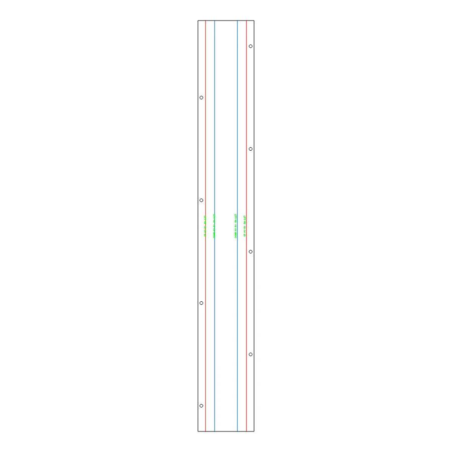
| Model | Read from | Unfolded as |
|---|---|---|
| A sheet-metal part (flats and round bends) | STEP (.step, .stp) as an exact solid: planar and cylindrical faces, as CAD programs and ParametrIQ's own STEP export write it |
Sheet metal: bend allowance, bend lines with notes, T, K and R |
| A carton, box or folded board (flat faces meeting at sharp creases) | STEP with flat faces, faceted or tessellated STEP, STL (.stl, text or binary), OBJ (.obj) or glTF (.glb, .gltf) |
A crease pattern: creases where faces meet, cut everywhere else |
A STEP file with round faces is tried as sheet metal first; if it isn't a sheet of one thickness it is unfolded as a board, its curved faces as narrow flat strips (said in the messages). Models are read as products are: STEP files give their own units (millimetres, inches, metres …) and an assembly's parts are put where it puts them; STL is taken as millimetres; OBJ as millimetres (metres if it is under 10 units across), Y up; glTF as metres, Y up. The drawing is made in your drawing units.
The options
| Option | What it does |
|---|---|
| Material | The sheet's material: its K-factor table gives each bend's K-factor at its own R / T (the list shows each material's at R = T). |
| K-factor | A K-factor of your own (0 to 1) for every bend instead of the material's table. |
Sheet metal
The part's faces are sorted into flats (planes) and bends (cylinders):
- Thickness T: the distance from the largest flat to the flat behind it, facing the other way.
- Inside radius R: each bend has two cylinders round one axis, T apart; the smaller is its inside.
- Angle: how far round its axis the bend's face goes.
- K-factor K: from the options (the model doesn't say where its neutral layer is): the material's table's at
each bend's R / T, else the K-factor given. The new drawing has the material's table as KTABLE and
K=KFACTOR(KTABLE,R,T), so a bend of another radius keeps its own K-factor.
One side of the sheet is laid flat, face by face from the largest flat: each flat as it is, each bend's strip as wide as its bend allowance, the angle × (R + K × T), as the Bend Line and Flat Pattern tools work it out. The side drawn is the one most bends go up from (a tie: the side whose largest flat faces up), so a part folded from a ParametrIQ drawing comes back as it was drawn.
The new drawing has:
- Its industry Sheet metal, and the variables T, K and R (R the radius most bends have).
- The blank's outline and its holes on the Cut layer: straight edges as lines, round holes as circles, arcs as arcs; an edge running slantwise across a bend as points along it.
- A bend line down the middle of each bend's strip, made as the Bend Line tool makes it: on the Crease layer for a bend up, the Reverse crease layer for a bend down, with its note (UP 90° R2 and its bend allowance) worked out from its own angle variable (BANG1 …) and R, K and T. A bend with another radius has its own number in its note.
So the drawing folds up again on a 3D page, its bend table lists its bends, and changing K or R changes the notes.
Where the pattern would overlap itself (flanges that run into each other once laid flat), the messages say so: check it before cutting.
Cartons and boards
A model made of flat faces is unfolded along the edges its faces share:
- A model with no thickness (a surface: each panel one face) is laid flat as it is.
- A model with board thickness (a closed solid: the inside and the outside of the board, and the narrow faces round its edges) is laid flat on one side: the narrow edge faces (no wider than the board, square to the faces beside them) are left out, and the faces joined to the largest one kept. T is set to the board's thickness.
- Faces are laid flat from the largest one, across the longest shared edges first. A face that would land on one already laid is tried across another of its edges; if none works, it starts a piece of its own beside the rest (the messages say how many pieces). So the pattern never overlaps itself.
- The edges it is laid across are its creases: on the Crease layer where the faces fold towards you as you look at the pattern, on the Reverse crease layer where they fold away. The side it is seen from is the one most creases fold up from, so a closed box is seen from inside, as dielines are drawn.
- Every other edge is cut (on the Cut layer).
- Glue and tuck flaps: a face lying flat against another face in the model is counted in the messages; it stays on the panel it folds from.
The drawing's industry is Packaging, so it can be checked with Check Dieline and folded on a 3D page.
Notes
- One part is unfolded at a time: a sheet-metal file with several separate blanks unfolds the one with the largest flat (the others are said to be left out); a board model's separate pieces are laid side by side.
- A sheet-metal part needs exact faces (planes and cylinders). A sheet-metal part saved as STL or OBJ (triangles only) is unfolded as a board, each bend as narrow strips with a crease between each.
- Bends must be cylinders: a cone or a rolled (B-spline) bend isn't unfolded.
See also: Sheet Metal and Living Hinges in 3D, STEP, Sheet Metal, Packaging.