Steel Structures
Build a steel structure from several drawings - a column, a beam, its end plates, a bracket - each drawn and detailed on its own, placed in one structure drawing by its grid and levels. The 3D page shows the whole structure with its bolts (where the pieces' holes line up) and its welds (from the weld map), exports it to IFC and STEP, and checks it against the architect's IFC model for clashes.
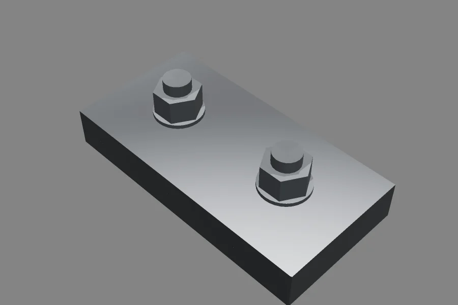
A structure drawing
A structure drawing places its members with PRODUCT statements, each naming another drawing
(.piq): kept in the structure drawing, or linked (read again whenever it is opened, so a changed member shows). Use
3D › Models and Products › Place Product… and choose the member's drawing. Each member is made 3D as its own 3D page shows it - its
plates and profiles, its own mates, its welds - and placed:
ORIGIN=TRUEputs the member drawing's own origin on the point, at the heightZ: so a column drawn standing on its origin goes on a grid point, a beam at its level. Without it the member is centred on its point and dropped onto what is under it, as a product in a pack is.ROTturns it about the vertical;TILTXandTILTYstand up a piece drawn lying down (a column's web drawn on the page:TILTY=-90).- Grid lines and levels are plain variables, so moving a grid line moves everything on it:
GRIDA=0,"Grid A"
GRID1=6000,"Grid 1"
LEVEL1=3200,"Level 1"
P1=[GRIDA,0]
P2=[GRIDA,GRID1]
PRODUCT @10,P1,"column.piq",5,ORIGIN=TRUE,TILTY=-90
PRODUCT @11,P2,"column.piq",5,ORIGIN=TRUE,TILTY=-90
PRODUCT @12,P1,"beam.piq",5,ORIGIN=TRUE,ROT=90,Z=LEVEL1
Members can also be put together with mates, as any parts can. A single steel drawing whose pieces are mated (a beam and its end plates on one page) is a structure too.
Bolts
Round holes cut in the pieces (circles on the Cut layer through a plate or a beam's web) that line up on one axis through two or more pieces get a bolt, its nut and its washers:
- Size: the drawing's bolt spec,
CLASSIFY "bolts","M20 8.8"(or aBOLTvariable holding the size, as the library's connections have); without one, the size the hole takes (EN 1090-2's normal holes: 1 mm over the bolt up to M14, 2 mm to M24, 3 mm from M27: a 22 mm hole takes M20). A member's own spec is used for its holes when the structure drawing has none. - Class: 8.8 unless the spec says (
10.9,4.6…).HVorHRin the spec: preloaded, a washer under the head as well. - Length: the grip (the pieces' thicknesses along it), its washers, its nut (ISO 4032) and two threads past the nut, made up to the next length bolts come in (… 50, 55, 60, 65, 70, 75, 80, 90, 100 …).
- Standard: ISO 4014 (part threaded) when its plain shank ends inside the grip, so the nut can be done up;
else ISO 4017 (threaded to the head).
ISO 4017in the spec asks for it. CLASSIFY "bolts","none"shows no bolts.
Pieces that don't meet where a bolt goes through them (a gap of more than 1 mm), a hole no bolt fits, or a bolt too big for its hole are said in the 3D page's message bar. Bolts move with the piece their head is on.
Welds
Each weld numbered with the Weld Number tool is shown along the edge of the piece its
leader points at, where that edge meets another piece (once the pieces are put together): a fillet on each side, its
leg from the weld's size (a5: a throat of 5 mm, a leg of 7.1; z7 or 7: a leg of 7; none: 5), or a cap on each
side for a butt weld. A weld whose leader points at no edge, or at an edge no other piece meets, is said in the
message bar. Welds numbered in a member's drawing come with the member.
Bolts and welds list
On the 3D page (or the drawing page it shows), choose 3D › Bolts and Welds…: the bolts listed by designation (ISO 4014 M20 × 60 - 8.8) with their nuts, washers, how many and their grips, and the welds with their type, leg, length and piece. Save keeps the list as CSV, a web page or text. The IFC export carries them too.
Exporting
File › Export › Export… › IFC Files (Steel Model) writes a structure as it stands (see IFC):
| In the structure | In the IFC model |
|---|---|
| A member's piece | An IfcBeam (a profile's piece) or IfcPlate, where it is, as a triangulated face set; its piece mark, profile and grade (IfcMaterial) |
| A bolt | An IfcMechanicalFastener (BOLT, its nominal diameter and length), Pset_MechanicalFastenerBolt, its designation, nut and washers (PiQ_Fastener), connecting the first two pieces it goes through (IfcRelConnectsWithRealizingElements) |
| A weld | An IfcFastener (WELD), Pset_FastenerWeld: its type and leg |
IFC models placed as a reference are left out. File › Export › Export… › STEP writes the whole structure, bolts and welds included, as the 3D page shows it.
The architect's model: IFC import and clashes
Place the architect's (or engineer's) IFC model with 3D › Models and Products › Place Product…, choosing the .ifc file, and give
it ORIGIN=TRUE (and Z=0) so it stays where it was modelled. IFC2X3 and IFC4 files written as STEP (.ifc) are
read:
- every element with a shape (walls, slabs, columns, beams, members, plates, doors, windows, roofs, stairs, furniture, proxies …); openings, spaces and the site are left out;
- placed through their chains of local placements, in the file's unit (millimetres, metres, feet …);
- swept solids (extruded rectangles, circles, hollow sections, I, L, U and T sections, and outlines with voids made of polylines, indexed poly curves and composite curves), faceted B-reps, triangulated and polygonal face sets, and mapped items (a type's shape placed again, scaled); a Boolean result is shown as its first solid (what it cuts away left on). Other shapes are left out and said.
The model is shown see-through (ifc-reference), so the steel shows inside it. It is checked against every member, as
a product is (Does it fit?): where a member runs into it, the clash is shown red and said in the
message bar with the elements that clash (arch.ifc: its parts that clash: Wall A, Roof); 3D › Models and Products › Show Product Fit…
lists them. Members are checked against each other the same way: pieces that only touch (a plate bolted to a flange)
don't count.
Notes
- A plate drawn without 3D settings is a flat blank in 3D: it lies where it is drawn, so its holes are found there. Welds are shown on pieces made solid (profiles, and bodies on a layer with 3D settings).
- Holes are round holes through a piece, square to its face; slotted holes and holes in flanges drawn on their own face pages aren't bolted.
- Bolts are hexagon bolts with plain washers; preloaded (HV) sets are shown with a washer each side.
See also: Structural steel, Products in the pack, Putting parts together, IFC.