Element settings
What every command that adds an element (LINE, ARC, POLYLINE, TEXT, DIMHORIZONTAL …) has in common: its id, its layer, and the settings that can follow it.
Syntax
KEYWORD @id,points…,layer,settings…
| Part | Meaning |
|---|---|
| @id | The new element's id: @ and a whole number (optional). Left out, the next free id is used. Give one when a later command needs to name the element (JOIN @1,@2, ONELEMENT(@1,0.5)). |
| points | The element's points, by name: P0, P12 … A point must already exist; make one with an assignment such as P4=[250,200]. |
| start | Where a command says its first point is optional (LINE, ARC, BULGE, CIRCLE, BEZIER, QUADRATICBEZIER, POINT, PARALLEL), leaving it out starts the element at the current point, #CP, which is normally P0. |
| layer | The layer's number, as in the Layers panel (optional). Left out, the current layer, #CL. |
| TRUE, FALSE | Yes or no settings, such as which way an arc runs. |
A list of points is written in square brackets: [P1,P4,P5] takes those points in that order, and [P1..P5] takes
P1, P2, P3, P4 and P5, just as if they were written out (and the drawing saves them written out: [P1,P2,P3,P4,P5]),
so moving, copying or mirroring the element takes every one of them.
Settings after the element
Any of these can follow an element, each after a comma, in any order:
| Setting | Meaning |
|---|---|
BRIDGES count,width |
Bridges (nicks) on the rule: how many, and how wide each is (see Bridging settings). |
LINEWIDTH w |
The line width to draw and print the element with. |
HIDDEN |
The element is not drawn. |
NOPLOT |
The element is left out of G-code and HP-GL. |
TOOL KEY=value,… |
Machining settings for G-code (see below). |
RULE KEY=value,… |
How far a crease folds in 3D (FOLD) and when (STEP), a bend line's press-brake tools (PUNCH, DIE), a part's own 3D settings (THICK, Z, LOOK, DEPTH, AS, and a wrapped piece's ON, DIA and AXIS), and die-making details kept from CF2 and DDES3 files (see below). |
TOOL settings
| Key | Meaning |
|---|---|
NO |
Tool number (the T word). |
NAME |
Tool description, written as a comment. |
DIA |
Cutter diameter. |
RPM |
Spindle speed. |
CW |
TRUE for the spindle clockwise (M3, the default), FALSE for anticlockwise (M4). |
FEED, PLUNGE |
Cutting feed and plunge feed, in units per minute. |
START, DEPTH |
Z of the material surface (default 0) and of the bottom of the cut (negative below the surface). |
STEP |
Deepest cut per pass (0: one pass). |
SAFE |
Z for rapid moves. |
SIDE |
"ON", "INSIDE", "OUTSIDE", "LEFT" or "RIGHT": which side of the line the cutter runs. |
COOLANT |
TRUE to turn coolant on (M8). |
DRILL |
TRUE to drill a hole at a point, or at a circle's centre. |
HOLE, PECK, DWELL |
Drill hole diameter, peck depth (G83), and seconds to wait at the bottom (G82). |
POCKET |
"ZIGZAG", "SPIRAL" or "CONTOUR": clear the inside of the closed element in that style instead of cutting along it (see Pocketing). |
STEPOVER |
For a pocket: the distance between passes (no more than the tool's diameter; left out, a share of the diameter the export options give). |
OVERCUT |
For a drag knife (HPGL): how far a closed cut runs on past its start (see HPGL). |
BLADE |
For a drag knife (HPGL): the blade's offset, how far its tip trails behind its axis. |
An element needs only the settings that differ from its layer's: each layer can have TOOL settings of its own
(LAYER …,TOOL KEY=value,…, see LAYER), set for all the layers at once in
Production › Tool Options. What an element is cut with is, for each setting, the first of:
- the element's own TOOL setting;
- its layer's;
- the export options' (the pocket layer and default tool of the G-code export).
So LINE P1,P3,0,TOOL FEED=600 on a layer with TOOL DIA=6,FEED=1200,DEPTH=-3 is cut with a 6 mm tool, 3 deep, at
600 a minute. DRILL=TRUE on a layer drills every element on it (a point, or a circle's centre). The
Properties panel's Tool Options… edits an element's own settings, and Use Layer Settings
clears them, so its layer's apply.
RULE settings
FOLD is how far a crease folds when the drawing is folded in 3D, in degrees from 0 to 180: RULE FOLD=60 for each
crease of a hexagonal carton, RULE FOLD=180 for a gusset folded flat. The line's layer still says which way it
folds (Crease one way, Reverse crease the other). A crease without it folds 90°. It can be worked out from the
drawing's sizes, and then follows them: RULE FOLD=180-RTOD(ATAN2(D,W/2)) for the base of a triangular tube.
STEP is when a crease folds as the design folds up: the creases with step 1 fold first, then step 2, and so on, so
a box's walls can stand up before its flaps close over them: RULE STEP=1 on the walls' creases, RULE STEP=2 on
the bottom flaps', RULE STEP=3 on the top's. Creases without a step take the one the 3D page's fold order gives them
(see Pages), numbered the same way, so a step of 1.5 comes between the order's first and second. Creases
with the same step fold together. It can be worked out too (RULE FOLD=90,STEP=S+1). On the 3D page, picking a crease
and choosing Set fold step writes it for you; so do dragging a panel to fold it (FOLD) and dragging creases and
steps on the fold-order timeline (STEP): see Live editing in 3D.
PUNCH and DIE name the press-brake punch and die a sheet-metal bend line is bent with (tools of the tooling
library: RULE PUNCH="Gooseneck punch 88°",DIE="V-die 16 mm 88°"); without them they are chosen. See
Press-Brake Simulation.
The others are kept from die-making files so they can be written back; you rarely type them. AUX and POINTAGE (CF2),
TABLE, QUALIFIER, CORNER, SEGMENT, SEGSTART, SEGEND (DDES3), FILELAYER and ARROWHEAD.
A part's 3D settings
A part is made 3D by its layer's LAYER3D settings: one thickness, height and material for every closed outline on the layer. A part that differs has its own, on its closed outline (or on a part or block whose outlines they are), over its layer's:
| Setting | Meaning |
|---|---|
THICK |
Its thickness: a 6 mm back drawn on the 18 mm boards' layer. |
Z |
The height of its underside: from the floor, or from the top of the bodies its layer sits on (ON). |
LOOK |
Its material: the id of an appearance ("birch-plywood", "oak", "glass-clear" …). |
DEPTH |
On a pocket, V-carve or groove: how deep it cuts, over its layer's DEPTH and its machining depth. |
AS |
"NONE" leaves it out of 3D: a second view of a part drawn twice (a leg's two faces), or a mate for a part not made. "WRAP" wraps it: see below. An expression is worked out as the variables change (AS=NSH>=5?"":"NONE"; "" as its layer says). |
For each one, the part's own setting wins; without it, its layer's; without that, the drawing's (the material's
thickness T, the 3D page's material). Each can be worked out from the drawing's variables, and then follows them:
RULE THICK=BT,LOOK="birch-plywood" makes a part BT thick, and changing BT changes it. In a
function, the function's own arguments can be used (RULE THICK=TK); a thickness of 0 is not
set, so a function can give its parts their own thickness or leave them their layer's.
RULE AS="WRAP" on one element of a closed outline wraps that piece alone (Wrapping and sweeping):
| Setting | Meaning |
|---|---|
ON |
The number of the element (@5: ON=5) whose line the piece is bent along, standing up on it: a duct's wrap stood on its cheek's curved edge. |
DIA |
Without ON: the diameter it is rolled round where it is drawn; a sector with its point drawn becomes its cone. |
AXIS |
With DIA: the direction, in degrees, of the axis it is rolled round, on the drawing (90, up the page, unless said). |
These settings only make the 3D model: no 2D export writes them, and the drawing cuts the same. Everything that uses a part's thickness follows them: its body and the cuts in it (a pocket deeper than the part goes only through it), its mates (a face's height is in the part's own thickness), fittings and banding, the 3D exports, measuring, and the panel cut list's thickness (see Reports). The Properties panel's 3D Part sets them for the selected parts.
Bridging settings
A rule's own bridges, which Make Die, CF2 and DDES3 files and the drawing API use (the Bridge Tool writes them for you):
| Setting | Meaning |
|---|---|
BRIDGES count,width |
That many bridges, spread evenly along the rule (round a closed one). |
RULE PLACED="C0.25:6 L0.75:6" |
Bridges at set places: each its style (C full height, L or R a tack on the left or right, D tacks both sides), its centre as a share of the rule's length (0 its start, 1 its end), and its width. They keep their share of the length as the rule changes. |
RULE BRIDGEWIDTH=w |
The width of the rule's bridges, over the widths PLACED and BRIDGES give. |
RULE BRIDGESPACING=d |
Bridges spread along the rule at most this far apart, instead of BRIDGES' count: a longer rule gets more. |
RULE BRIDGEENDS=d |
The first and last bridge this far (their centres) from the ends of the rule, the others evenly between. |
RULE BRIDGEPAIR=g |
Each bridge doubled: two, this gap between them. |
BRIDGEWIDTH, BRIDGESPACING, BRIDGEENDS and BRIDGEPAIR can be worked out from the drawing's variables
(RULE BRIDGEWIDTH=BRW1), and then follow them.
Examples
P4=[250,200]
LINE @1,P0,P4,1
LINE P4,P2,0,BRIDGES 2,3,LINEWIDTH 0.5
POINT P4,0,TOOL DRILL=TRUE,HOLE=5,DEPTH=-12
LINE P1,P3,0,HIDDEN,NOPLOT
LINE @5,P0,P1,1,RULE FOLD=60
LINE @6,P1,P2,1,RULE STEP=2
BRW=5,"Bridge width"
LINE @7,P0,P4,0,RULE PLACED="C0.25:5 L0.75:5",BRIDGEWIDTH=BRW
LINE @8,P4,P2,0,BRIDGES 3,4,RULE BRIDGEENDS=10,BRIDGEPAIR=2
LINE @9,P2,P0,0,RULE BRIDGESPACING=60,BRIDGEWIDTH=BRW
POLYLINE @10,[P0,P1,P4],TRUE,0,RULE THICK=6,Z=12,LOOK="birch-plywood"
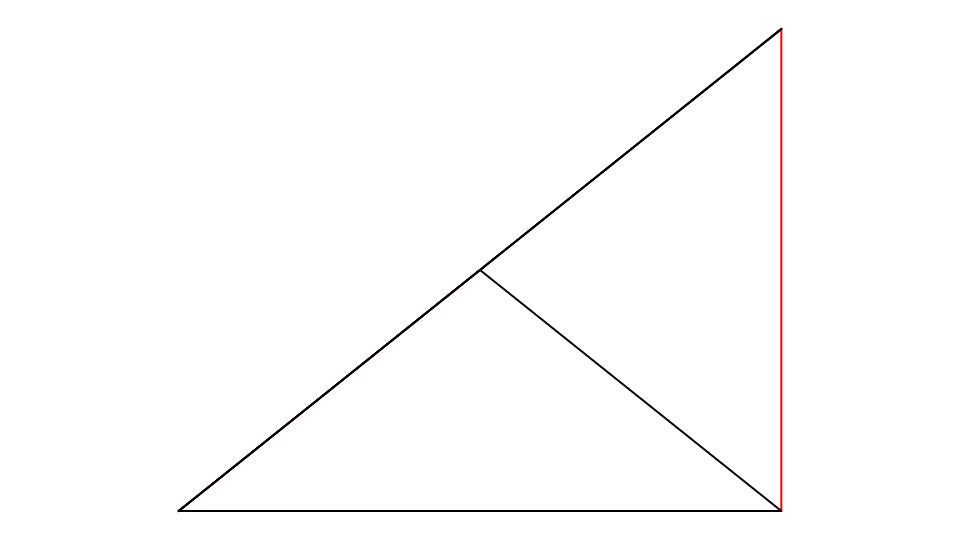
The first line is on layer 1 (Crease); the second is a cut with two 3 mm bridges, drawn 0.5 wide; the point is a 5 mm hole drilled 12 deep; the next line is neither drawn nor plotted; the next is a crease that folds 60° (one side of a hexagon); the next folds in the second step. The last three are cuts with bridges of their own: two at a quarter and three quarters of the way along (the second a tack), as wide as BRW; three pairs, the first and last 10 from the ends; and as many as keep them no more than 60 apart. The triangle is a part 6 thick in birch plywood, 12 off the floor in 3D, whatever its layer says.
Notes
Everything an element is made from is a point or an expression, so the element follows its points when they move. Its settings are written after it in the drawing file exactly as typed here, and the Properties panel shows and changes them.
An element made in a block (a loop, an IF, a function) keeps its layer, LINEWIDTH, BRIDGES,
TOOL and RULE settings in what the block makes. A fold angle, step or part's 3D setting worked out from the block's
variables is worked out as each element is made, so creases made in a loop (RULE FOLD=A for each A) each fold as
far as their own turn says. A HIDDEN element in a block isn't drawn.