Properties
The Properties panel shows the settings of the selected elements, and changes them. Open it from View › Panels › Properties if it is closed. At the top it says what is selected: the element's kind and id, or how many elements. Under that, All settings shows or hides the settings most people rarely need, and Show all properties shows every section, whether or not it applies to the selection (see Simple mode).
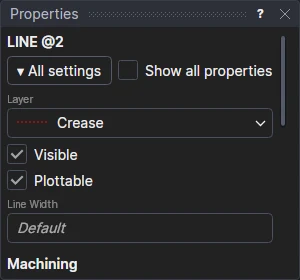
Every element
- Layer: the layer the elements are on.
- Visible: untick to hide the elements. A hidden element isn't drawn, even on a visible layer, and isn't exported.
- Plottable: untick to leave the elements out of G-code and HP-GL, even on a layer that is plotted.
- Line Width: the width of the line drawn, in drawing units; leave it blank for the default.
A picture's source
With only pictures selected (raster or vector), the Source part shows where they came from:
- File or web address: the file (relative to the drawing's folder where it is in it) or address. Change it to link linked pictures to another source; an embedded picture only remembers it.
- Embed in drawing: ticked, the picture is kept inside the drawing; cleared, it is linked, read from its source whenever the drawing is opened. Tick it to keep the copy last read; clear it to link the picture (it needs a source).
- How the link stands (read, being read, not found, not allowed), and Update, which reads the source again.
See Linked files and web addresses.
Machining
What the elements are cut with in G-code: their own tool settings, or, when they have none, their layer's (set in Production › Tool Options), or the export's defaults.
- Tool Options… opens the elements' own settings, grouped as in the layers' grid: tool, speeds and feeds,
depths, cutter side and coolant, drilling, pocketing. A blank box isn't set: the element is cut with what is shown
greyed in it, its layer's setting (
Layer: 6) or the export's default. Type a value to give the elements their own; clear one to go back to the layer's. With several elements selected, a setting they differ on shows Various and is left as each has it unless you change it. OK changes them all as one step to undo. - Use Layer Settings (here, in the Tool Options dialog, and on the drawing's right-click menu when a selected element has settings of its own) clears the elements' own settings, so they are cut with their layers'. One step to undo.
The settings are the element's TOOL settings (see Element settings).
Bridges
Shown when some of the selected rules have bridges (nicks) of their own: put on with the
Bridge Tool, or read from a CF2 or DDES3 file. It says what they ask for (how many and how
wide, how many placed, at most how far apart, how far from the ends, doubled), a size worked out from a variable
with its name (6 (BRW1)); Their bridges differ when the selected rules ask for different ones.
- Clear Bridges takes the selected rules' own bridges off, one step to undo: Make Die then bridges them automatically again.
The bridges are the element's BRIDGES and RULE settings (see
Element settings).
3D Part
Shown when the selection has closed outlines, parts or blocks: their own settings for the 3D page, over their layer's. A blank box takes the layer's, shown greyed in it (From the layer: 18); with several parts selected that differ, Various.
- Thickness: how thick the part is in 3D.
- Offset (underside height): how high its underside is, from the floor (or from the bodies its layer sits on).
- Material: its look, an appearance's id (
oak,birch-plywood…). - Cut depth: for a pocket, V-carve or groove, how deep it cuts.
- Leave out of 3D: the part isn't made 3D (a second view of a part drawn twice).
Type a number or an expression of the drawing's variables (BT, T/3): the part then follows them. Each change is
one step to undo, and the 2D drawing and its exports are not changed. They are the element's RULE THICK, Z,
LOOK, DEPTH and AS settings (see Element settings).
Fills
When only fills are selected (see the Fill Tool): what they are filled with (Fill with), and for a hatch its Spacing, Angle and Cross-hatch; for a solid fill its Colour (or The layer's colour); for a gradient its kind, First and Last colour (a four-corner gradient: its bottom left and bottom right ones) and what it does Beyond the ends.
A nest
When a nest is selected: its Copies wanted (a number, or a variable such as QUANTITY;
blank for one sheet), and what the nest comes to as the drawing is now: the copies on a sheet, the sheets the copies
wanted take, the copies made and spare, and the wastage, a sheet's and the run's.
Dimensions and callouts
When only dimensions (or callouts, or magnifiers) are selected, their Dimension text settings are shown too. A blank box shows,
greyed, the drawing's dimension setting variable it follows (#DFS …): leave it
blank and the dimension keeps following the variable, so it changes when the variable does; type a value or an
expression (#DFS*2) for the dimension to have its own.
- Text: for callouts, the text in the box; for magnifiers, the text under the callout.
- Height: the height of the capital letters (
#DFS). - Font Type and Font: a vector font (an .shx file, or blank for the built-in font) or a TrueType font (an
installed family, offered as you type, or a .ttf or .otf file) (
#DFK,#DFN). Default follows the variable. - Bold and Italic: for TrueType fonts. The third, filled state follows the variable (
#DFB,#DFI). - Character Width: how wide the letters are, 1 normal (
#DFW). - Decimal places: the most shown, 0 to 10 (
#DDP). - Dimension Arrow Size (
#DAS), Dimension Gap (#DGP: between the points and the extension lines, and the dimension line and its text) and Dimension Extension (#DEX: how far extension lines run past the dimension line). - Distance to dimension line: for horizontal, vertical and aligned dimensions, how far out the dimension line is
(
#DD). - Caption (<> for the value): text instead of the measurement, with
<>standing for it; leave it blank to show the measurement.
Depends on and Used by
Whatever is selected, elements or points, the panel ends with what it is worked out from and what is worked out from it:
- Depends on: the Points it is drawn on or defined from, and the points those are defined from, all the way
back (through the elements points are defined on, and the parts they are placed from); and the Variables any of
them name, with the variables those are worked out from (
FLAP=L/4brings inL). Change any of these, and the selection follows. Select These Points selects them, to see where they are or to edit them. A selected point isn't listed as its own, unless a selected element is drawn on it. - Used by: the Points defined directly from the selection, and the Elements drawn on the selected points or worked out from the selected elements: what changes with it, and what deleting it would affect (see Points).
A point fixed in space depends on nothing: Check Parametric lists those.
Several elements
With several elements selected, a setting they share is shown; one they don't is blank (or, for a check box, neither ticked nor clear), and setting it sets it for all of them. Press Enter, or leave a box, to apply what you typed. Each change is one step to undo.
See also: Layers, Element settings.