Living Hinge Tool
Use the Living Hinge Tool to fill a band of a panel with a living hinge (a kerf-bend lattice): rows of slots, every other row staggered by half a slot, so the strips between the rows twist a little each and a stiff sheet bends round a curve.
Usage
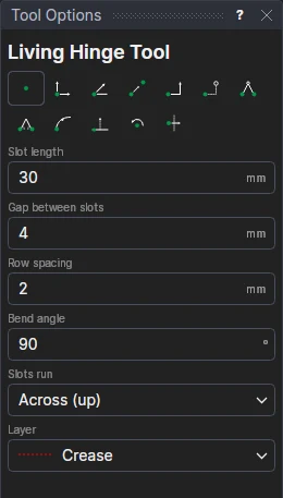
- Fill in the Slot Length, the Gap Between Slots (the bridge left between slots in a row), and the Row Spacing (from one row to the next: about the sheet's thickness, or a little less, for plywood).
- Fill in the Bend Angle: how far the hinge bends in 3D, in degrees (more than 0 up, towards you; less than 0 down).
- Choose which way the Slots Run: Across (up) the band, to bend it round an upright axis, or Along it.
- Choose the layer to draw on (the cut layer).
- Mark* one corner of the band to bend, then the opposite corner. The band is shown as you move.
The closed rows have whole slots with a bridge at each side of the band; the staggered rows run out to its sides, so the band bends as a whole. The rows are centred in the band.
A hinge that follows the drawing
The slots are a FOR block on the two corners and on new variables: the slot length (LHL1), gap (LHG1), row spacing (LHS1) and bend angle (LHA1). Move a corner and the band fills again; change a variable and the lattice changes. The boxes then show the variables, so the next hinge shares them.
In 3D
On a 3D page the band bends round to its bend angle, as a curved bend does: folded between the rows of slots, in one step. See Sheet metal and living hinges in 3D.
See also the Living-hinge panel design in Run Parametric's Laser cutting folder.
*Depending on the chosen snap mode, several clicks may be required to define the point parametrically. Read more about Snap Modes