Segmented Bend Tool
Use the Segmented Bend Tool for a bend made of straight pieces cut at an angle: a pipe's mitred (lobster-back) bend, or a round duct's gored elbow. The cuts are the same - each is (R + r·cos θ)·tan(a) from the piece's middle - so it is one tool with two Kinds: One wrap-round template (the Mitre Segment: one piece's template to wrap round a pipe and mark it) or All gores laid out (the Elbow Gores: every gore developed flat, with its collar and seam allowance, ready to cut from sheet). Its button is Mitre Segment for pipework and Elbow Gores for HVAC and sheet metal.
Which kind for which trade
| Kind | The trade's own tool | A drawing for |
|---|---|---|
| One wrap-round template | Mitre Segment Tool | pipework, HVAC |
| All gores laid out | Elbow Gores Tool | HVAC, sheet metal |
A drawing for one industry starts with its trade's kind, and the toolbar button has that kind's name; a General drawing (or Show All Tools) shows the button as the Segmented Bend tool. The kind you choose stays chosen for that drawing until you choose another. The Tool menu still lists each trade's tool by its own name. Each kind makes what its trade's tool always has made: the same lines, layers and variables.
Each kind keeps its own sizes and variables (MSD1 …, EGD1 …): the Mitre Segment's bend radius is in diameters and counts the joints; the Elbow Gores' radius is a length and counts the pieces (one more than the joints).
Mitre Segment Tool
Use the Mitre Segment Tool to draw the wrap-round cutting template of a piece of a mitred or lobster-back (segmented) bend: print it full size, wrap it round the pipe or duct, and mark along the curves. It is a tool of the pipework and HVAC trades.
Usage
- Choose the Piece: a Middle segment (cut at both ends) or an End segment (square at one end).
- Fill in the Pipe Diameter (outside), the Bend Radius (× Diameter) to the bend's centre line (1.5 for a long-radius bend), the Bend Angle, and the number of Joints: the cuts across the bend. A mitred elbow has 1 (two end segments); a lobster-back with three middle segments has 4.
- For an end segment, fill in the Straight: how much straight pipe it has beyond the bend.
- Set the number of Segments each curve is drawn in (72 to start with).
- Choose the layer to cut on.
- Click* where the template starts, then a point along the way it runs. The curves are shown as you move.
The template is as long as the pipe's circumference (π × its diameter). Its sides are where the back of the bend is (the longest), its middle where the throat is; the quarter lines go on the Crease layer (if the drawing has one), to line the template up with the bend's back, throat and sides. Cut as many middle segments as the joints less one, and two end segments.
The cut
Each cut is a = bend angle ÷ (2 × joints) off square. On the line along the pipe at θ round it from the back of the bend, it is
(RB + r cos θ) × tan a
from the segment's middle (a middle segment, both ways) or from its straight (an end segment), for the pipe's radius r and the bend's radius RB. A middle segment's back is 2 (RB + r) tan a long, its throat 2 (RB − r) tan a.
It follows the drawing
The diameter, the bend's radius, angle and joints, and the straight are kept in new labelled variables (MSD1, MSR1, MSA1, MSJ1, MSS1), and the template is drawn by a block on the two points you marked: change a variable, or move a point, and it follows.
*Depending on the chosen snap mode, several clicks may be required to define the point parametrically. Read more about Snap Modes
See also: Pipe Saddle, Reducer, Elbow Gores, Pipework.
To print the template full size, marked for wrapping round the pipe (angles, centre lines, an overlap strip, its girth), use File › Export › Export… › Wrap-around templates (PDF): see Wrap-around templates.
Elbow Gores Tool
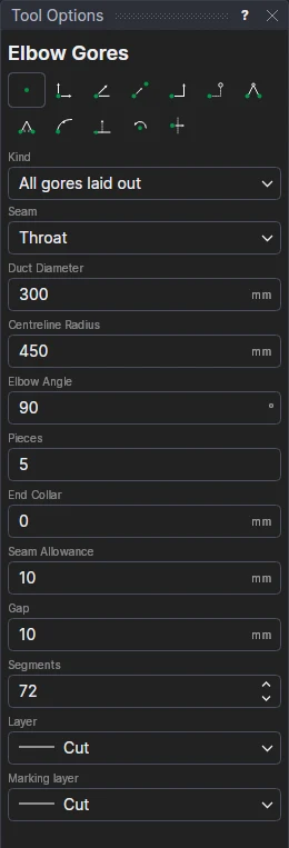
Use the Elbow Gores Tool to draw the flat patterns of all the gores (segments) of a segmented round elbow, laid out ready to cut from sheet, roll and join. It is a tool of the HVAC and sheet-metal trades. (For a wrap-round template to mark one segment on a pipe, use the Mitre Segment tool.)
Usage
- Choose where the Seam goes round the duct: at the Throat (the inside of the bend, where the gores are shortest), at the Heel (the outside, where they are longest) or at a Side.
- Fill in the Duct Diameter, the Centreline Radius (from the centre of the bend to the duct's centre line: more than half the diameter; 1.5 × the diameter is usual), the Elbow Angle, and the number of Pieces: the gores the elbow is made of, its two end gores among them (a 90° elbow is often 5 pieces; 2 pieces make a plain mitre).
- Fill in the End Collar: a straight added at each end gore's square end, for the connection (0 for none); the Seam Allowance: a lap added beyond each gore's closing edge, folded on its line (0 for none, for a butt weld); and the Gap left between the gores.
- Set the number of Segments each cut line is drawn in (72 to start with; made a multiple of 4).
- Choose the layer to cut on and the Marking layer (the Crease layer, if the drawing has one).
- Click* where the layout starts, then a point along the way the gores' stretch-out runs. The first end gore is shown as you move.
The gores are laid out one above the other, to the left of that line: the first end gore (its square end on the line), the middle gores, and the last end gore (turned the other way, its square end at the top). Each is as long as the duct's circumference (π × its diameter), its two sides the seam. The lines at the heel, the throat and the sides go on the marking layer, to line the gores up when they are joined, with the seam allowances' folds and the end gores' collar lines.
The cut
An elbow of N pieces has two end gores and N − 2 middle gores. Each middle gore turns the elbow through θ = elbow angle ÷ (N − 1); each end gore through half that, so it is a half gore. A gore is a length of the duct cut at each end by a plane through the centre of the bend, θ/2 either side of its middle. On the line along the duct at φ round it from the heel, each cut is
h(φ) = (R + r·cos φ)·tan(θ/2)
from the gore's middle (an end gore's square end), where R is the centreline radius and r the duct's radius. On the flat pattern each cut line is h plotted along the stretch-out, φ = 2π × (distance from the seam) ÷ circumference, starting from the seam's angle. Sizes are developed as typed: for a thick sheet type the mean diameter (inside plus the thickness).
Worked example
A Ø300 duct, 90° elbow of 5 pieces on a 450 centreline radius, seam at the throat: θ = 90° ÷ 4 = 22.5°, so each middle gore is 2 × (450 + 150) × tan 11.25° ≈ 238.7 long at the heel and 2 × (450 − 150) × tan 11.25° ≈ 119.3 at the throat (its sides); each end gore is half that. Every gore is π × 300 ≈ 942.5 round.
It follows the drawing
The diameter, centreline radius, angle, number of pieces, collar, seam allowance and gap are kept in new labelled variables (EGD1, EGR1, EGA1, EGN1, EGC1, EGS1, EGG1), and the gores are drawn by a block on the two points you marked: change a variable (even the number of pieces), or move a point, and they are drawn again.
*Depending on the chosen snap mode, several clicks may be required to define the point parametrically. Read more about Snap Modes
See also: Mitre Segment, Rectangle to Round, HVAC, Sheet Metal.